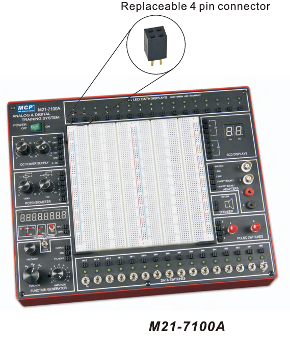
M21-7100A ANALOG & DIGITAL TRAINING SYSTEM
BDT 47,023/-
Product Details
Feature
-
High level, high quality digital‑analog trainer
-
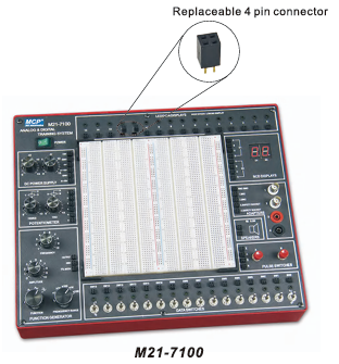
Replaceable 4 pin connector, easy to maintenance
-
Combines all essential function of analog and digital experiment
-
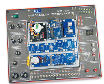
With removable breadboard, DC power supply, function generator, two pulse switches, 2 1/2 inch 8 ohm 0.5W speaker and etc.
Specification
-
SOLDERLESS BREADBOARD: Interconnected with 2820 tie points nickel plated contact, fitted all DIP sizes and all components with lead and solid wire AWG #22‑30 (0.3‑0.8mm). It can be changed and replaced for different purpose and can be connected with demonstration panel. Therefore, it is very convenient for both teachers and students.
-
DC POWER SUPPLY: A. Fixed DC output: +5V, 1A B. Fixed DC output: -5V, 1A C. Variable DC output: 0V to +15V, 1A D. Variable DC output: 0V to -15V, 1A
-
POTENTIOMETERS: A. Variable resistor VR1 = 1kΩ B. Variable resistor VR2 = 100kΩ
-
FUNCTION GENERATOR: (A) Frequency range: 10Hz–10Hz, 10Hz–100Hz, 100Hz–1kHz, 1kHz–10kHz, 10kHz–100kHz (B) Amplitude Sine wave output: 0–10 Vpp variable Triangle wave output: 0–10 Vpp variable Square wave output: 0–10 Vpp variable TTL mode output: 4 Vpp
-
SIXTEEN BITS DATA SWITCHES: 16pcs toggle switches and corresponding output point. When switch is set at “down” position, the output is LO level; contrariwise, it is the HI level while setting at “up” position.
-
TWO PULSE SWITCHES: (WITH 2 SET OF OUTPUT: (A, A̅, B, B̅)) 2pcs pushbuttons contain switches debouncer for eliminating the bounce caused by switch from “open” to “close” or from “close” to “open” position.
-
SPEAKER: 2‑1/2 inch diameter, 8 ohm/0.5W to be used for load.
-
FOUR CHANNEL ADAPTOR: Both of the two banana sockets and two BNC jacks’ point pins are changeable. It is suitable for M21‑7000 to be connected with peripherals.
-
TWO DIGITS OF 7 SEGMENT LED DISPLAY: (A) Output display Numerical designs and resultant displays
(B) Function tables (0–15 values with HI/LO logic outputs)
-
SIXTEEN BITS LED DISPLAY: 16 red LEDs separate input terminals. The LED will be lighted up when input is at “HI level” and it will be turned off when it is at input or at “LO level”.
-
OTHER STANDARD ACCESSORIES: (1) Power cord (2) Pin: 10pcs/20cm 20pcs (3) User manual
-
INPUT VOLTAGE: 110–127VAC±10% 60Hz, 220–240±10% 50Hz Switchable
-
DIMENSIONS (W×H×D): 334×95×258mm
-
WEIGHT: 4.5kg
| SOLDERLESS BREADBOARD: | Interconnected with 2820 tie points nickel plated contact, fitted all DIP sizes and all components with lead and solid wire AWG #22‑30 (0.3‑0.8mm). It can be changed and replaced for different purpose and can be connected with demonstration panel. Therefore, it is very convenient for both teachers and students. |
| DC POWER SUPPLY: |
A. Fixed DC output: +5V, 1A B. Fixed DC output: -5V, 1A C. Variable DC output: 0V to +15V, 1A D. Variable DC output: 0V to -15V, 1A |
| POTENTIOMETERS: |
A. Variable resistor VR1 = 1kΩ B. Variable resistor VR2 = 100kΩ |
| FUNCTION GENERATOR: |
(A) Frequency range: 10Hz–10Hz, 10Hz–100Hz, 100Hz–1kHz, 1kHz–10kHz, 10kHz–100kHz (B) Amplitude Sine wave output: 0–10 Vpp variable Triangle wave output: 0–10 Vpp variable Square wave output: 0–10 Vpp variable TTL mode output: 4 Vpp |
| SIXTEEN BITS DATA SWITCHES: | 16pcs toggle switches and corresponding output point. When switch is set at “down” position, the output is LO level; contrariwise, it is the HI level while setting at “up” position. |
| TWO PULSE SWITCHES: |
(WITH 2 SET OF OUTPUT: (A, A̅, B, B̅)) 2pcs pushbuttons contain switches debouncer for eliminating the bounce caused by switch from “open” to “close” or from “close” to “open” position. |
| SPEAKER: | 2‑1/2 inch diameter, 8 ohm/0.5W to be used for load. |
| FOUR CHANNEL ADAPTOR: | Both of the two banana sockets and two BNC jacks’ point pins are changeable. It is suitable for M21‑7000 to be connected with peripherals. |
| TWO DIGITS OF 7 SEGMENT LED DISPLAY: |
(A) Output display Numerical designs and resultant displays (B) Function tables (0–15 values with HI/LO logic outputs) |
| SIXTEEN BITS LED DISPLAY: | 16 red LEDs separate input terminals. The LED will be lighted up when input is at “HI level” and it will be turned off when it is at input or at “LO level”. |
| OTHER STANDARD ACCESSORIES: |
(1) Power cord (2) Pin: 10pcs/20cm 20pcs (3) User manual |
| INPUT VOLTAGE: | 110–127VAC±10% 60Hz, 220–240±10% 50Hz Switchable |
| DIMENSIONS (W×H×D): | 334×95×258mm |
| WEIGHT: | 4.5kg |
Feature
-
High level, high quality digital‑analog trainer
-
Replaceable 4 pin connector, easy to maintenance
-
Combines all essential function of analog and digital experiment
-
With removable breadboard, DC power supply, function generator, two pulse switches, 2 1/2 inch 8 ohm 0.5W speaker and etc.
Specification
-
SOLDERLESS BREADBOARD: Interconnected with 2820 tie points nickel plated contact, fitted all DIP sizes and all components with lead and solid wire AWG #22‑30 (0.3‑0.8mm). It can be changed and replaced for different purpose and can be connected with demonstration panel. Therefore, it is very convenient for both teachers and students.
-
DC POWER SUPPLY: A. Fixed DC output: +5V, 1A B. Fixed DC output: -5V, 1A C. Variable DC output: 0V to +15V, 1A D. Variable DC output: 0V to -15V, 1A
-
POTENTIOMETERS: A. Variable resistor VR1 = 1kΩ B. Variable resistor VR2 = 100kΩ
-
FUNCTION GENERATOR: (A) Frequency range: 10Hz–10Hz, 10Hz–100Hz, 100Hz–1kHz, 1kHz–10kHz, 10kHz–100kHz (B) Amplitude Sine wave output: 0–10 Vpp variable Triangle wave output: 0–10 Vpp variable Square wave output: 0–10 Vpp variable TTL mode output: 4 Vpp
-
SIXTEEN BITS DATA SWITCHES: 16pcs toggle switches and corresponding output point. When switch is set at “down” position, the output is LO level; contrariwise, it is the HI level while setting at “up” position.
-
TWO PULSE SWITCHES: (WITH 2 SET OF OUTPUT: (A, A̅, B, B̅)) 2pcs pushbuttons contain switches debouncer for eliminating the bounce caused by switch from “open” to “close” or from “close” to “open” position.
-
SPEAKER: 2‑1/2 inch diameter, 8 ohm/0.5W to be used for load.
-
FOUR CHANNEL ADAPTOR: Both of the two banana sockets and two BNC jacks’ point pins are changeable. It is suitable for M21‑7000 to be connected with peripherals.
-
TWO DIGITS OF 7 SEGMENT LED DISPLAY: (A) Output display Numerical designs and resultant displays
(B) Function tables (0–15 values with HI/LO logic outputs)
-
SIXTEEN BITS LED DISPLAY: 16 red LEDs separate input terminals. The LED will be lighted up when input is at “HI level” and it will be turned off when it is at input or at “LO level”.
-
OTHER STANDARD ACCESSORIES: (1) Power cord (2) Pin: 10pcs/20cm 20pcs (3) User manual
-
INPUT VOLTAGE: 110–127VAC±10% 60Hz, 220–240±10% 50Hz Switchable
-
DIMENSIONS (W×H×D): 334×95×258mm
-
WEIGHT: 4.5kg
The M21‑7100 Analog & Digital Training System is a versatile electronics lab trainer designed for both analog and digital circuit experiments. Featuring a removable solderless breadboard, dual DC power supplies, function generator, pulse switches, LED displays, and integrated speaker, it provides a complete platform for students and instructors to explore circuit design, logic operations, and mixed‑signal applications. Compact and durable, the M21‑7100 is ideal for classrooms, laboratories, and hands‑on electronics training.
Asked by Visitor
100% Viscose Fabric.
Thank You.
Asked by Visitor